Concrete Lifting Anchors: Strength Limit States
Concrete Lifting Anchors: Strength Limit States
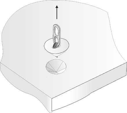
An anchor can fail by:
Anchor Failure failure of the anchor itself or its reinforcing elements (e.g. hanger bars)
Concrete Failure where the concrete surrounding and supporting the anchor fails
Safe design requires that all strength limit states for each type of failure be considered
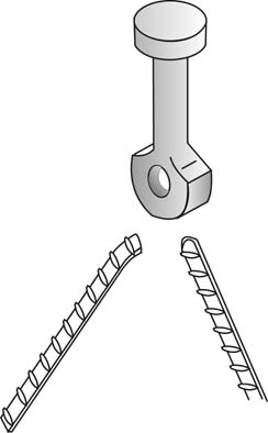
Anchor Failure
The anchors may fail in a number of ways and the limit states must be assessed by design and / or verified by test for anchors to comply with AS3850 (AS4100, AS3600 as applicable).
|
|
|
|
|
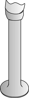
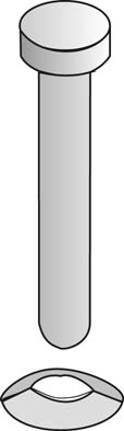
| Spherical Head Anchor Systems |
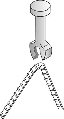
Hairpin Anchor Systems |
||
| STRENGTH LIMIT STATE |
FAILURE Spherical Head anchors |
FAILURE Hairpin anchors |
Design Calculation |
Test method |
|---|---|---|---|---|
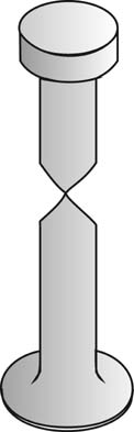
| Anchor body failure |
|
|
AS4100 and AS3850 WLL=ΦNtf /2.5 |
AS3850 Appendix 2. Clutch+Anchor Tension Test (out of concrete!) |
|
STRENGTH LIMIT STATE |
FAILURE Spherical Head anchors |
FAILURE Hairpin anchors |
Design Calculation |
Test method |
|---|---|---|---|---|
| Lifting attachment point failure |
|
|
No reliable method |
AS3850 Appendix 2. Clutch+Anchor Tension Test |
| Embedded part failure |
|
|
AS4100 and AS3850 WLL=ΦNtf /2.5 |
AS3850 Appendix 2. Clutch+Anchor Tension Test |
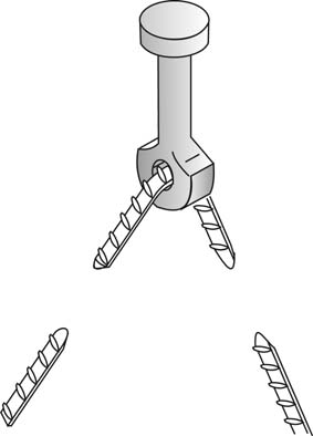
| Hanger attachment point failure “pull-through” of the bar |
|
|
No reliable method to calculate the bending-shear failure strength of the anchor. |
Clutch+Anchor+Rebar Tension Test (out of concrete!) |
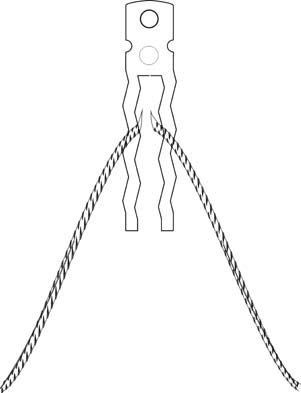
Anchor Failure: Hanger Bar failure
Hanger bars are required when the lifting load exceeds the WLL of the Concrete Strength.
| STRENGTH LIMIT STATE |
FAILURE Spherical Head “Eye” anchors with hanger |
FAILURE |
Design Calculation |
Test method |
|---|---|---|---|---|
| Hanger bar shear failure |
|
|
No reliable method to calculate the bending-shear failure strength of the reinforcing bar. |
Appendix 2. Clutch+Anchor |
| Hanger bar tension failure |
|
AS3600 and AS3850 WLL = Φ*Ru / 2.5 The Limit state is the ultimate bar strength Ntf = Ab x1.05 x fsy since Ru = Ntf and Φ=0.8 for steel Total WLL for 2 legs: WLLhanger bar = 2 ΦNtf / 2.5
|
use characteristic strength |
|
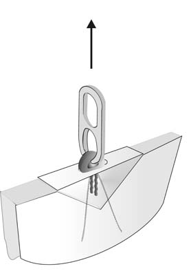
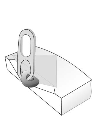
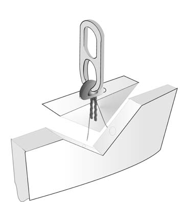
CONCRETE FAILURE
| STRENGTH LIMIT STATE |
All Anchors placed well away from edges - “cone” failure |
Anchors placed in edges - “pie” shaped partial cone |
Design Calculation |
Test method |
|---|---|---|---|---|
| Concrete Cone failure |
|
|
Empirical from tests |
Appendix 2. Embedded anchor Tension test |
| |
Appendix 2. Embedded anchor Tension test |
|||
| Hanger bar pullout |
|
AS3850 and AS3600. Length to develop bar in the concrete below the crack from the foot of the anchor. Leg Lst = Lsyt where Lsy.t =k1 k1 fsy Ab / (2*a + db) √ f’c and Lsy.t ≥ 25k1db |
Not Required |
|
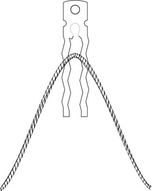
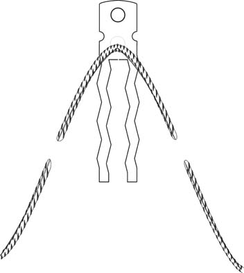
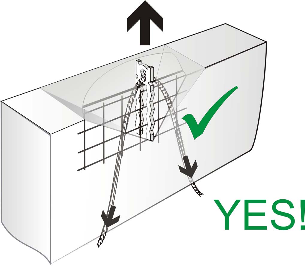
HANGER REINFORCING BAR DETAILING
| Hangers must extend downwards below the crack to shed the load deep within the panel. The required “leg length” is calculated according to AS3600 to develop the strength of the bar. Note: AS3850 requires that the strength of the anchor exceeds 2.5 X WLL of the anchor. The bar forms part of the anchor itself and therefore its strength must meet this requirement for all its strength limit states. NB: the limit state strength of the bar may not be limited by its tensile strength only! |
|
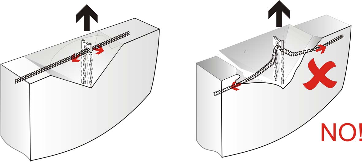
| DO NOT USE HORIZONTAL e.g. Trimmer bars! Horizontal bars do not increase the pullout strength of the anchor !
|
|
Typical hanger bar dimensions and how they are calculated.
The development depth required for each hanger leg to share the load is calculated from the using AS3600 clause 13.1.2.1 to develop the strength of the bar.
An N16 bar is required for anchor working loads up to 7.1Tonnes
An N20 bar is required for anchor working loads up to 9Tonnes
The following diagram shows a hanger bar detail designed for lifting 150mm thick panels when demoulding at 10MPa.
This is the recommended standard detail for all 7, 8 and 9 tonne hanger bars, regardless of anchor type or make (applicable for both hairpin and spherical head “eye” anchors).
© 2007 Hillside Engineering